
1. Introduction
BUT Ultra-thin AAO Template
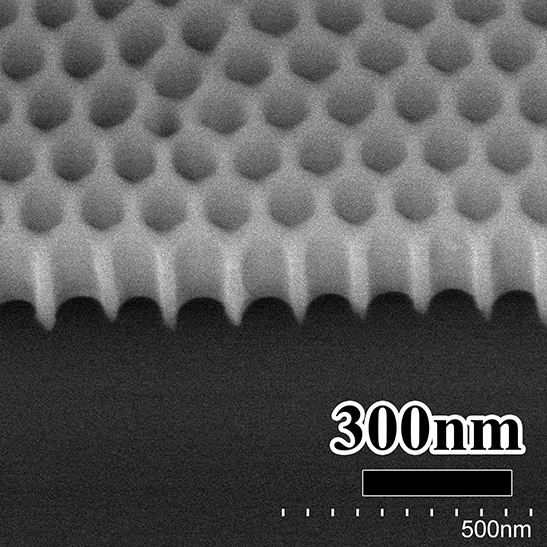
Ultra-thin AAO (Anodic Aluminum Oxide) template, or ultra-thin porous nano template, its pores are double-pass AAO structure, is a single-pass AAO template to remove its barrier layer, their thickness is only tens to hundreds of nanometers, widely used in the preparation of nanodot arrays, nanowire arrays, etc. and substrate surface patterning. The ultra-thin AAO template has uniform pore diameter, short-range and orderly hole arrangement, and the material of alumina makes it transparent in the visible light band and electrically insulated. Compared with other graphical nanostructure preparation methods (such as lithography, electron beam exposure, focused ion etching), the unique advantage of ultra-thin AAO templates is that they can easily obtain microstructures down to the nanometer level within the square centimeter range, and their cost is low compared with electron beam lithography and focused ion beam etching.
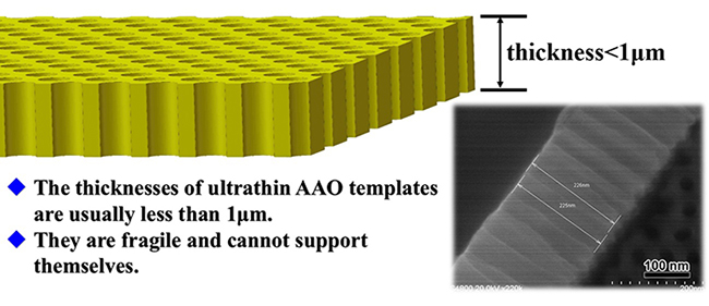
Figure 1. (top left) Schematic diagram of ultra-thin AAO template product structure; (bottom right) SEM diagram of an ultra-thin AAO template section.
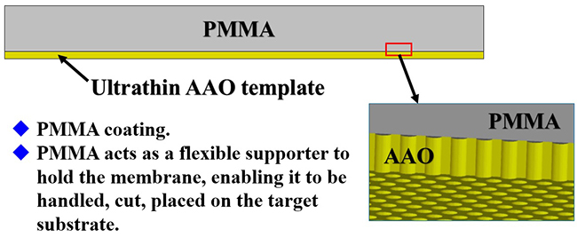
Figure 2. Schematic diagram of PMMA/AAO composite membrane structure.
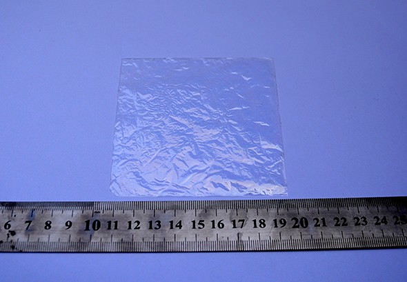
Figure 3. A large area of PMMA/AAO film
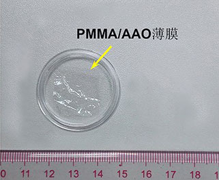
Figure 4. A typical AAO ultra-thin film product photo
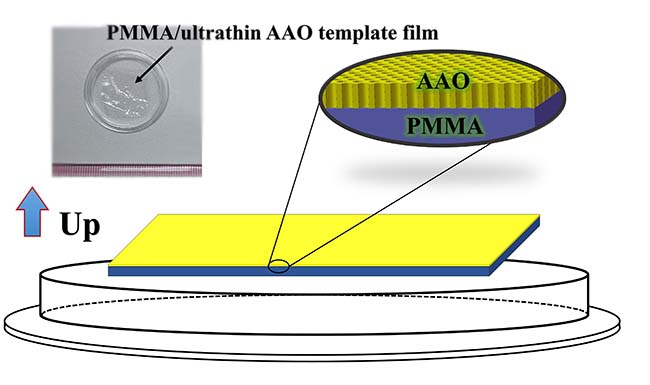
Figure 5. Slim AAO template physical drawing and product placement diagram
One disadvantage of ultra-thin AAO templates is that they are difficult to operate (unlike single-pass porous nanotemplates that have aluminum-based supports), because AAO is not self-supporting when the thickness is less than 1 micron, as shown in Figure 1, and is very fragile and very inconvenient to use. We apply a layer of PMMA to the surface of the ultra-thin AAO template as support, as shown in Figure 2, which can be easily accessed, cut, and transferred to any target substrate. With the help of PMMA membrane, a large-area ultra-thin AAO template can be obtained, as shown in Figure 3. Carefully cut the large area membrane to obtain an ultra-thin AAO template with a smaller area, the actual photo is shown in Figure 4. The PMMA side of the inner membrane of the box is facing down and the AAO side is facing up, as shown in Figure 5.
2. on the transfer of ultrathin films
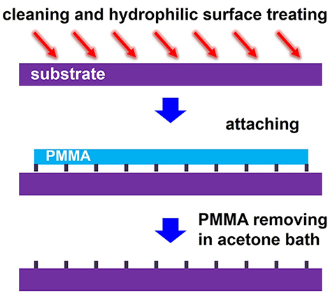
Figure 6. Schematic diagram of the transfer principle of ultra-thin AAO template
Ultra-thin AAO templates generally need to be transferred to the target substrate, and Figure 6 shows the principle of a transfer method for ultra-thin AAO with a PMMA support layer. First, the target substrate is cleaned and hydrophilic, so that AAO will fit more evenly and closely with the substrate. (Note: In fact, for silicon wafers, quartz sheets, glass sheets, etc., as long as they are cleaned and not hydrophilic, it is okay, but the fit between AAO and the substrate is slightly worse, and it does not have much effect.) Hydrophilic treatment can be cleaned with low-power oxygen (or air) plasma, or treated with a UV surface treatment machine. If these devices are not available, the substrate can be treated with a piranha (piranha) solution, which allows the substrate to be clean and hydrophilic at the same time, but with safety when operating.
The PMMA/AAO is then cut to the desired shape and size and placed on top of the substrate. The PMMA support layer can be removed with acetone, during which the ultra-thin AAO template will be bonded to the substrate. After removing PMMA, do not touch the surface of the AAO ultra-thin film because the ultra-thin AAO is fragile, so as to avoid AAO damage. All containers and countertops must be cleaned in advance during the transfer operation.
Regarding the organic substrate: Please make sure that the substrate is not soluble in acetone, otherwise it will cause transfer failure.
About Ultra Film Transfer Services:
If you do not want to transfer ultrathin films yourself, we also provide ultra-thin film transfer services with the substrate provided by the customer. When sending the substrate, please attach a description of the substrate, including the material, form, handling precautions, and ultra-thin film model corresponding to the substrate. Please clean the substrate after cutting before mailing, the packaging substrate should ensure that we are easy to take out, if the substrate surface is easily damaged, you can fix it with narrow width (such as 3~5mm) double-sided adhesive at the bottom of the box, do not use conductive carbon glue. If there is more substrate than enough, you can mail a few additional substrates for later use. For specific transfer charges, please contact our customer service.
Transfer is charged according to the number of substrates, not the number of AAO membranes, for example, if one AAO is cut into 2 pieces and transferred to 2 substrates, it is regarded as 2 transfer operations, because regardless of the size of the membrane, the transfer time is basically the same. For ultra-thin films with a pore spacing of 450nm, the substrate must be a polished substrate, or a glass substrate, which means that the surface must be flat and bright, and we do not provide transfer services for non-polished substrates. Base size, round must be less than or equal to 1 inch, square must be less than or equal to 20*20mm, larger than this substrate we do not provide transfer services. In addition to the general silicon wafers, other substrates are provided by customers, and the sending substrate can send a few more pieces for backup.
Note: When PMMA/AAO is soaked in acetone, there are two ways for PMMA to disappear, one is to break quickly and fall off from the AAO, and the other is not broken, but slowly dissolves, both of which may be encountered and unpredictable. Therefore, see the membrane rupture and fall off after putting in acetone, don't worry, that is the PMMA membrane broken, not AAO film, irradiate it with a flashlight on the side, look closely, you can clearly see the AAO membrane.
Since the ultra-thin surface transferred to the substrate surface cannot be touched, we generally use double-sided adhesive to fix the substrate to the bottom of the box when packaging after transfer. Be careful when taking out, use tweezers to gently pry at the edge of the substrate to separate the substrate from the double-sided adhesive, if it is still not easy to pry, you can add a little ethanol to the edge of the substrate to temporarily lose the viscosity of the double-sided adhesive, and the substrate can be easily removed by gently plucking or prying.
Tips: Ultra-thin AAO templates with a thickness of less than 200nm are very fragile, and it is easier to crack when transferring and using, so when choosing an ultra-thin AAO template with a thickness of less than 200nm, you must be cautious, such as the size of the transfer area of 15mm*15mm, and local micro-damage is normal. In addition, in the process of transfer use, it is best to cut the membrane into smaller pieces for use, such as 5*5mm, the smaller the membrane area, the smaller the possibility of rupture of the membrane and the degree of rupture.
Note: If the PMMA surface is attached to the substrate, after the PMMA is removed, the front side of AAO is in contact with the substrate, because most of the AAO front holes and holes are convex structures, so at this time the contact surface between AAO and the substrate is relatively small, and the bond with the substrate becomes weak, and it is expected that AAO may be easier to stick off with tape in the later stage.
About the small size transfer method:
If your substrate is small, such as less than 10*10mm, such as 5*10mm, you can use the "fishing" method.
First of all, put the glass beaker or crystal dish containing acetone (the crystal dish is better, the mouth is relatively large) in the fume hood, the general crystal dish diameter is 60mm, the depth is three or four centimeters, the depth is shallow and easy to operate. The fume hood table top should be wiped clean, the table top is black, and then find an LED flashlight, the kind that focuses, do not use the lighting of the mobile phone, the mobile phone lighting has no beam. The flashlight does not need to be very advanced, the focus does not need to be very good, there is a beam on the line, from the side to illuminate a clean glass crystal dish with clean acetone, with a beaker because it is too deep, it is not easy to operate, the glass crystal dish mouth is large, there is relatively shallow, will not block the tweezers, from the side to irradiate a clean glass crystal dish with clean acetone, and then a clean black desktop as the background, the fume hood fan should be turned on (acetone hurts the body, do not inhale acetone), the light of the fume hood is turned off, the side of the flashlight is illuminated to turn on the flashlight, So the instrument is ready.
For example, your substrate is 7*7mm, you can cut PMMA/AAO with clean scissors to cut out a piece of 7*9mm PMMA/AAO, note that PMMA/AAO is slightly larger than the base, because later in the fishing time there will be a part of AAO on the side around the side of the substrate or/and back, of course, it can also be 7*10mm, 8*10mm, so that AAO in one dimension is greater than the minimum side length of the substrate.
After cutting the PMMA/AAO, put it in acetone, note,when you put it, the AAO side is up, the PMMA side is down,it's the same way it is placed in the box.After being placed in acetone, the PMMA/AAO membrane sinks to the bottom of the container. The flashlight shines on the side, you can clearly see the PMMA/AAO sheet, adjust the position of the beam, and make the observation more clear and convenient. After a few minutes, the AAO and PMMA will be partially separated. At this time, gently turn the container, or gently shake the container, or gently stir the acetone in the container with tweezers holding the base, in order to make the acetone in the upper part of the AAO form a certain flow.
You can put in PMMA/AAO and leave acetone alone, let acetone dissolve the PMMA statically, and shake it after a few minutes. AAO and PMMA separation is gradual, first separated from the edge, when shaking, the flowing acetone will bring up a part of the detached AAO, the flashlight is shining on the side, you can see the AAO part up. Part of the AAO stood up. After a few minutes to ten minutes, the AAO is completely separated from PMMA. After separation, AAO will float in levitation in acetone with the flow of acetone, and the flashlight is shining on the side, which can be observed AAO, which is very soft. Hold the substrate with sharp-nosed forceps, the flashlight is shining on the side, the fume hood light is kept off (the environment should be darker), and gently agitate acetone with forceps pinching the base to find the AAO membrane that sees the suspension swimming.
When scooping, the substrate is slightly inclined, and one edge of the substrate (the horizontal edge at the top after tilting) is used to "pick" one edge of the AAO membrane. "Pick" is to use a line to pick a surface, this line is a side of the base, the surface is the AAO membrane, that is, let the AAO "ride" on the substrate. The wrong operation method is to place the substrate horizontally and try to put the AAO flat, because with the flat end, the AAO will slide off the substrate due to the flow of acetone when the substrate approaches the liquid level. And if you use one side of the base to "pick" or "grab" one of AAO's heads, you can catch it. The substrate remains tilted, and the rest of the AAO on the grabbed side is laid on the substrate surface when the substrate lifts off the acetone level. It can be carefully experienced when operating. Never attempt to flatten the AAO membrane with a substrate larger than the AAO area, trying to have the AAO membrane in the center of the substrate. After scooping it out, wait for the acetone to evaporate and dry, and then put the base into a second cup of clean acetone. At this time, AAO and the substrate will not be separated. Then, soak for ten minutes (time can be adjusted), take it out to dry, and soak in a third cup of clean acetone. Soak for a while, take it out to dry, and then it will work.
Tip: Do not put AAO in water or aqueous solution after transferring the AAO to the substrate, otherwise it may fall off. Ultra-thin AAO templates cannot be cleaned ultrasound, otherwise they will be completely broken.
Pictures of ultra-thin AAO templates transferred to some substrate surfaces:
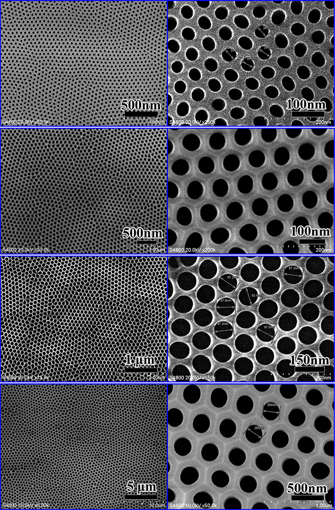
Figure 7. SEM diagrams of several typical ultra-thin AAO templates.
(Note that the pore size uniformity and arrangement order of ultra-thin AAO templates are relatively poor compared to single-pass and double-pass thick films. The picture above is an electron microscopy of the selected area and sample. The quality of ultra-thin AAO products also fluctuates to a certain extent, please be aware before purchasing to avoid psychological gaps)
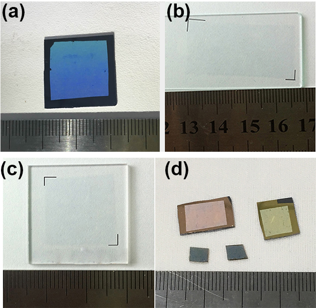
Figure 8. Transfer to (a) silicon wafer (b) glass slide (c) quartz glass (d) other substrate surfaces. (a,d) are ultrafilms with a pore spacing of 450 nm, and (b,c) are ultrafilms with a pore spacing of 100 nm.
Note: (a) The ultrafilm with a pore spacing of 450 nm is shown in the figure, and the blue appearance is due to the low angle white light irradiation on the side, and its color is very light blue close to white under natural light, as shown in Figure (d).
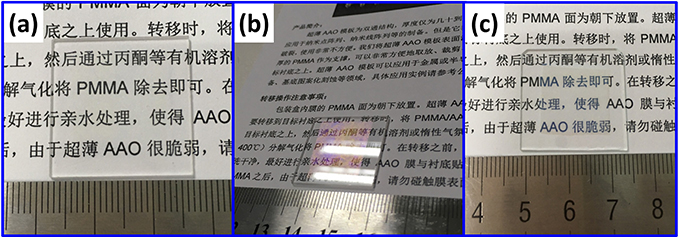
Figure 9. Close-range light transmission of ultra-thin AAO templates. (a,b) AAO, quartz sheet substrate with small pore spacing; (c) Pore spacing 450nm, ordinary glass substrate
Figure 7 shows the SEM diagram of several typical specifications of ultra-thin AAO templates. Figure 8 shows a photograph of an ultra-thin AAO template transferred to some substrate surfaces. You can see that since AAO is thin, the transparency is high. Ultra-thin AAO templates with a hole center spacing of 65 nm, 100 nm, and 125 nm are colorless, and ultrathin films with a hole center spacing of 450 nm are light blue (white light irradiation on the sides). Ultra-thin AAO template has good light transmission, such as ultra-thin AAO with a hole center spacing of 65nm, 100nm, and 125nm, and the front side looks almost invisible to the naked eye. The photo after transfer to the glass substrate is shown in Figure 9.
Using a similar method, ultra-thin AAO can be easily transferred to Si, sapphire, quartz glass, ordinary glass, SiC, ZnO, GaN, ITO, FTO, STO AND OTHER SUBSTRATE SURFACES. For PDMS substrates, although they can also be transferred, it is not yet known exactly whether PDMS reacts with acetone to cause the substrate surface to dissolve, so flexible organic substrate transfer is likely to cause problems.
Tips for depositing metal methods: Electron beam evaporation is recommended to prepare nanoparticles on substrates using ultra-thin AAO film as a mask template, because of its good evaporation directionality. Magnetron sputtering directionality is not good, it is difficult not to reach nanoparticles, and AAO is easy to roll up from the substrate when sputtering, so try not to use magnetron sputtering method, please know.
About physical evaporation:
The ultra-thin AAO template can be heated to five or six hundred degrees, but if heated to a higher temperature, cracks may appear in the ultra-thin film due to differences in expansion coefficient, so high-temperature experiments need to be cautious.
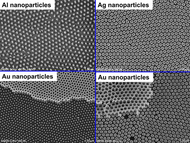
With ultra-thin AAO as a mask version, the deposition of metallic or semiconductor nanomaterials can be performed to obtain nanomaterial lattices, as shown in Figure 10. Therefore, nanowire arrays can be grown with metal nanolattices as catalysts, and nanopit arrays can be prepared on the substrate surface by direct etching.
When selecting ultra-thin AAO for the preparation of nanoparticles by physical evaporation, the ratio of pore diameter to film thickness is generally 1:3~1:6 (the pore spacing of 450nm can be 1:1). If the AAO film is too thin, the film is easily damaged during operation, and the adhesion of AAO to the substrate may be too strong; If it is too thick, the material vapor will not easily reach the substrate. When using porous membranes as templates and vacuum evaporation methods (such as electron beam deposition, thermal evaporation) to prepare nanoparticles, as the thickness of metal deposition increases, the deposited film will gradually make the pores smaller, and the thickness will continue to increase, and eventually the pores will be completely blocked. The metal film should not be too thick during deposition, the relationship between ultra-thin AAO structural parameters, deposition thickness and the shape of the obtained nanoparticles, due to the limitation of the deposition principle, the prepared nanoparticles are smaller than the pore size.
Note: Ultrathin films using electron beam evaporation methods to prepare nanoparticles need the substrate normal against the metal evaporation source, that is, the flight direction of the metal atoms must be parallel to the normal direction of the substrate, or the flight direction of the metal atoms is parallel to the direction of the axis of the AAO pore, so that the metal vapor can pass through the pores to reach the substrate, which is very important and must be paid attention to.
As you know: using ultra-thin AAO film as a mask template to prepare nanoparticles on the substrate, electron beam evaporation is recommended because of its good evaporation directionality, and it is not recommended to use methods such as magnetron sputtering and other poor directionality.
After evaporation of the metal, AAO can be glued off with tape, it is recommended to use polyimide high-temperature tape or 3M470 electroplating tape (the latter is better). First, slowly apply the tape to the surface of the sample, then gently press the entire surface with your fingertips to fully bond the tape to AAO, and then slowly peel off the tape. Note that the evaporation metal should not be too thick, such as AAO with a pore size of tens of nanometers, the thickness of the general evaporation metal is twenty or thirty nanometers, if it is too thick, the AAO is more difficult to stick down. The coating thickness with a pore size of two or three hundred nanometers can be thicker.
For ultra-thin AAO templates with pore spacing 100nm and 125nm, when the pore size reaches 80nm and 90nm respectively, the membrane due to inhomogeneity, a small number of micron-level pores will appear locally, the closer the pore size is to the hole spacing, the larger the hole will be, so the choice of ultra-thin AAO template with a pore diameter close to the hole spacing is to be cautious, of course, these holes account for a relatively small proportion, generally will not affect the experiment.
Note: The hole center spacing minus the hole diameter is not less than 30nm, and the film thickness is not less than 200nm, it is not easy to break.
Tips: AAO template is prepared by bottom-up method, belongs to self-organizing structure, so its pore size has a certain distribution range, not a single value, especially the hole spacing 450nm template is slightly more uniform, you must pay attention when choosing AAO. The holes are arranged in short-range orders (micron range), and each ordered region can be called a "chip", and the shape of the hole at the chip boundary may not be exactly circular. Ultrafilms have a wider pore size distribution than double-pass thick films and single-pass films. If you have very, very high requirements for the uniformity of pore size of porous membranes and very, very high requirements for the roundness of pores, then AAO is not a good choice, you can choose another top-down processing method.
Note: The AAO template is prepared by bottom-up method, so the pore size distribution has a certain width, not a single value marked in the quotation, the larger the hole spacing, the larger the aperture dispersion range. For ultra-thin AAO film, its dispersion range is wider than single-pass AAO, pore spacing 100nm, 125nm ultra-thin film, pore size dispersion width up to 20nm, for ultra-thin film with pore spacing 450nm, pore dispersion range is generally 60nm, occasionally, the minimum maximum pore size difference of individual can reach 90nm, the pore size change range marked in the quotation is the main range, such as pore size 260~310nm, which means that after testing at different positions of the entire large-area film, Most of the pore sizes are in this range, but occasionally there are individual areas where the pore size deviates from this range, such as individual pore sizes reaching 340nm, which is normal. When testing the aperture of the AAO template, be sure to choose different positions, multiple positions to test, fully reflect the size of the entire AAO aperture, and take high-magnification photos, avoid only measuring one or two positions, only take one or two pictures, only take low-magnification photos and then draw conclusions. Please be aware of the above precautions before purchasing. AAO template pore size has a certain distribution, ultra-thin AAO template distribution range is wider, users who require very accurate pore size should be cautious before selection.
For ultra-thin AAO with a film thickness of less than 200nm, because it is too thin, fragile, and easy to break and fold during transfer, it is recommended to cut it into small pieces for use (such as an area of 5*7mm), and transfer it to a relatively small substrate by fishing method. When fishing, do not try to use the substrate to flatten the AAO, be sure to tilt the substrate slightly, use one side of the substrate to pick a corner of the ultra-thin AAO, let one corner of AAO hang (or pick) the edge of the substrate, and then slowly raise the substrate to the liquid level. Note that ultra-thin AAO is fragile, easy to break and fold, and the operation should be careful and patient.
About the folds: On the one hand, because AAO is soft and ultra-thin, just like sticking a large piece of free plastic wrap to a steel plate, because the plastic wrap is not tensioned and flattened, so wrinkles are difficult to avoid; On the other hand, there may be some plastic deformation in some positions of AAO itself, causing wrinkles. The fold position AAO membrane is at a certain distance from the substrate, so it belongs to the defect position. Please be aware before purchasing.The substrate can be hydrophilic before transfer, such as silicon wafers, glass, sapphire, quartz, etc. can be soaked in a sulfuric acid mixture (piranha solution) for hydrophilic treatment to increase the adhesion between AAO and the substrate, thereby reducing folds.
Ultra-thin AAO is wrinkled after transfer to the substrate, it is difficult to achieve complete flatness without wrinkles, in addition, during the ultra-thin film transfer process, it is inevitable that some small areas will be folded or damaged, these are inherent defects of the sample, please be aware before purchasing, if you mind, please purchase with caution.
About the late removal of ultra-thin AAO: Ultra-thin AAO is generally removed after the metal is deposited, or after dry etching, and the problem that may be encountered is that AAO cannot be removed or cannot be completely removed. The method we recommend using is the tape method: Use brown high-temperature tape or 3M470 electroplated tape (3M470 electroplated tape is better), slowly stick to the AAO surface, press with your fingertips to make full contact between the tape and AAO, and then slowly peel off the tape.There are many reasons why AAO can not be glued, one of the main reasons is that the metal deposition is too thick, the thickness of ultra-thin film deposition metal with a hole center spacing of not more than 125nm should not exceed 25nm, the deposition thickness of 15nm or 20nm is appropriate, and the pore spacing of 450nm has not yet appeared this problem; Another reason is that if the sample is subjected to high temperature (such as greater than 400 degrees), the AAO and the substrate may sinter, resulting in sticking; Another reason is the substrate itself, and some substrates themselves are very adherent to AAO.This situation is difficult to predict and will only be known when it is actually done, so for substrates other than silicon wafers, sapphires, and glass sheets, this problem should be taken into account. Don't worry about whether the tape will stick the metal nanoparticles, because the tape will not touch the metal nanoparticles, and sometimes even directly stick with the tape a few times, the first exposed nanoparticles will not be glued off, according to the actual situation.
If you do not use the tape sticking method, you can use NaOH (5~10wt%, room temperature, the time is ten minutes to half an hour) or phosphoric acid (5~10wt%, 40~70 degrees, the time is uncertain, generally more than one hour), NaOH is more corrosive, we do not recommend using the solution method, because the solution method often contaminates the sample, and after AAO is dissolved, the metal nanoparticles or metal film on the surface of AAO are likely to adhere to the sample surface to cause secondary pollution.
If you really want to use the solution method, the recommended operation method is: the sample after depositing the metal film is buckled on the surface of the solution, the reverse side down, let it float, if it can't float, the sample is first attached to the foam plastic plate, and then buckled on the surface of the solution, the dissolution process can be properly shaken to shake the sample and solution, so that when the AAO is dissolved, the metal film or metal particles on the surface will fall down, off the sample surface and fall and sink to the bottom of the container, sometimes with the naked eye can see the flocculent falling, Those are the metal particles or metal film metal mesh on the AAO surface.
The solution method is not very mature and needs to be improved according to the actual situation. The solution method may also have the problem of incomplete AAO removal (sometimes the metal film metal particles adhered to the sample surface and caused by the illusion), a possible reason is that the metal deposition is too thick, and the thickness of ultra-thin film deposition with a pore spacing of no more than 125nm should not exceed 30nm; Another reason may be that if the sample is treated at a high temperature (e.g., greater than 600 degrees), the AAO will undergo a phase change and become a phase that is more resistant to acid and alkali corrosion, making it difficult to remove with NaOH or phosphoric acid.
In actual experiments, in fact, the removal rate of AAO will not reach 100%, and there will always be some deviations from the ideal. If the AAO is thicker (say not less than 200nm), it is easier to get rid of some. In short, when selecting ultra-thin AAO to prepare nanoparticles or dry etching, you may encounter AAO that cannot be removed or cannot be removed, please be aware before purchasing and using.
Ultra-thin AAO products are not as perfect as imagined, please know before purchasing, if you mind, please buy with caution:
(1) There are folds on the transfer of ultra-thin AAO to the substrate, and it is inevitable that there is a gap between the AAO and the substrate in the fold area, and the final sample prepared will be defective in the fold area.
(2) Because ultra-thin AAO is fragile, it is inevitable that there will be small folding and damage during the transfer process.
(3) The ultra-thin AAO pore size is more uneven than that of single-pass and double-pass thick films, that is, the pore size distribution is uneven on the entire sample surface, and some pores are large and some pores are small. The SEM plot in the product description and the prepared nanoparticles were taken from the selected better areas of the sample, and not the entire surface was completely consistent and uniform.
(4) Because each customer's experimental conditions are different, the suggestions we give may not be able to achieve your experimental purpose, and the actual use also requires customers to explore the process according to their actual situation.
For internaltional orders, please ask us for quotes via
Email: contact@scimaterials.cn
Tel: +86 15375698751
Wechat: SCI-Materials-Hub
Clik here to put quick orders on our Alibaba shop
BUT Ultra-thin Transplantation of AAO Membranes | |||
Product code | Aperture/pore depth | Price & Specifications | Inventory |
| 31103043 | 60-80nm/60nm | $66/pcs; 15*15mm | Ask for quote |
| 31103044 | 70-90nm/130nm | $66/pcs; 15*15mm | Ask for quote |
| 31103045 | 70-90nm/200nm | $66/pcs; 15*15mm | Ask for quote |
| 31103046 | 50-70nm/250nm | $66/pcs; 15*15mm | Ask for quote |
| 31103047 | 60-80nm/250nm | $66/pcs; 15*15mm | Ask for quote |
| 31103048 | 70-90nm/250nm | $66/pcs; 15*15mm | Ask for quote |
| 31103049 | 90-110nm/400nm | $66/pcs; 15*15mm | Ask for quote |
| 31103050 | 70-90nm/400nm | $66/pcs; 15*15mm | Ask for quote |
| 31103051 | 95nm/130nm | $90/pcs; 15*15mm | Ask for quote |
| 31103052 | 70nm/150nm | $90/pcs; 15*15mm | Ask for quote |
| 31103053 | 80nm/150nm | $90/pcs; 15*15mm | Ask for quote |
| 31103054 | 70nm/200nm | $90/pcs; 15*15mm | Ask for quote |
| 31103055 | 80nm/200nm | $90/pcs; 15*15mm | Ask for quote |
| 31103056 | 80nm/250nm | $90/pcs; 15*15mm | Ask for quote |
| 31103057 | 60nm/200nm | $90/pcs; 15*15mm | Ask for quote |
| 31103058 | 60nm/300nm | $90/pcs; 15*15mm | Ask for quote |
| 31103059 | 70nm/300nm | $90/pcs; 15*15mm | Ask for quote |
| 31103060 | 80nm/300nm | $90/pcs; 15*15mm | Ask for quote |
| 31103061 | 70nm/400nm | $90/pcs; 15*15mm | Ask for quote |
| 31103062 | 80nm/400nm | $90/pcs; 15*15mm | Ask for quote |
| 31103063 | 90nm/400nm | $90/pcs; 15*15mm | Ask for quote |
| 31103064 | 100nm/400nm | $90/pcs; 15*15mm | Ask for quote |
| 31103065 | 95nm/520nm | $90/pcs; 15*15mm | Ask for quote |
| 31103066 | 60nm/700nm | $90/pcs; 15*15mm | Ask for quote |
| 31103067 | 60nm/900nm | $90/pcs; 15*15mm | Ask for quote |
SCI Materials Hub Is Committed to Offering The Best Price & Customer Services! | |||
Worldwide shipping via DHL, SF-Express & other requested carriers.
Payments via Bank Transfer, Paypal, Credit card (via Alibaba), Alipay, Wechat-pay are accepted.
Partial references citing our materials (from Google Scholar)

Carbon Dioxide Reduction
1. ACS Nano Strain Relaxation in Metal Alloy Catalysts Steers the Product Selectivity of Electrocatalytic CO2 Reduction
The bipolar membrane (Fumasep FBM) in this paper was purchased from SCI Materials Hub, which was used in rechargeable Zn-CO2 battery tests. The authors reported a strain relaxation strategy to determine lattice strains in bimetal MNi alloys (M = Pd, Ag, and Au) and realized an outstanding CO2-to-CO Faradaic efficiency of 96.6% with outstanding activity and durability toward a Zn-CO2 battery.
2. Front. Chem. Boosting Electrochemical Carbon Dioxide Reduction on Atomically Dispersed Nickel Catalyst
In this paper, Vulcan XC-72R was purchased from SCI Materials Hub. Vulcan XC 72R carbon is the most common catalyst support used in the anode and cathode electrodes of Polymer Electrolyte Membrane Fuel Cells (PEMFC), Direct Methanol Fuel Cells (DMFC), Alkaline Fuel Cells (AFC), Microbial Fuel Cells (MFC), Phosphoric Acid Fuel Cells (PAFC), and many more!
3. Adv. Mater. Partially Nitrided Ni Nanoclusters Achieve Energy-Efficient Electrocatalytic CO2 Reduction to CO at Ultralow Overpotential
An AEM membrane (Sustainion X37-50 Grade RT, purchased from SCI Materials Hub) was activated in 1 M KOH for 24 h, washed with ultra-purity water prior to use.
4. Adv. Funct. Mater. Nanoconfined Molecular Catalysts in Integrated Gas Diffusion Electrodes for High-Current-Density CO2 Electroreduction
In this paper (Supporting Information), an anion exchanged membrane (Fumasep FAB-PK-130 obtained from SCI Materials Hub (www.scimaterials.cn)) was used to separate the catholyte and anolyte chambers.
SCI Materials Hub: we also recommend our Fumasep FAB-PK-75 for the use in a flow cell.
5. Appl. Catal. B Efficient utilization of nickel single atoms for CO2 electroreduction by constructing 3D interconnected nitrogen-doped carbon tube network
In this paper, the Nafion 117 membrane was obtained from SCI Materials Hub.
In this paper, Proton exchange membrane (Nafion 117), Nafion D520, and Toray 060 carbon paper were purchased from SCI Materials Hub.
7. National Science Review Confinement of ionomer for electrocatalytic CO2 reduction reaction via efficient mass transfer pathways
An anion exchange membrane (PiperION-A15-HCO3) was obtained from SCI Materials Hub.
8. Catalysis Communications Facilitating CO2 electroreduction to C2H4 through facile regulating {100} & {111} grain boundary of Cu2O
Carbon paper (TGPH060), membrane solution (Nafion D520), and ionic membrane (Nafion N117) were obtained from Wuhu Eryi Material Technology Co., Ltd (a company under SCI Materials Hub).
Batteries
1. J. Mater. Chem. A Blocking polysulfides with a Janus Fe3C/N-CNF@RGO electrode via physiochemical confinement and catalytic conversion for high-performance lithium–sulfur batteries
Graphene oxide (GO) in this paper was obtained from SCI Materials Hub. The authors introduced a Janus Fe3C/N-CNF@RGO electrode consisting of 1D Fe3C decorated N-doped carbon nanofibers (Fe3C/N-CNFs) side and 2D reduced graphene oxide (RGO) side as the free-standing carrier of Li2S6 catholyte to improve the overall electrochemical performance of Li-S batteries.
This paper used more than 10 kinds of materials from SCI Materials Hub and the authors gave detailed properity comparsion.
The commercial IEMs of Fumasep FAB-PK-130 and Nafion N117 were obtained from SCI Materials Hub.
Gas diffusion layers of GDL340 (CeTech) and SGL39BC (Sigracet) and Nafion dispersion (Nafion D520) were obtained from SCI Materials Hub.
Zn foil (100 mm thickness) and Zn powder were obtained from the SCI Materials Hub.
Commercial 20% Pt/C, 40% Pt/C and IrO2 catalysts were also obtained from SCI Materials Hub.
3. Journal of Energy Chemistry Vanadium oxide nanospheres encapsulated in N-doped carbon nanofibers with morphology and defect dual-engineering toward advanced aqueous zinc-ion batteries
In this paper, carbon cloth (W0S1011) was obtained from SCI Materials Hub. The flexible carbon cloth matrix guaranteed the stabilization of the electrode and improved the conductivity of the cathode.
4. Energy Storage Materials Defect-abundant commercializable 3D carbon papers for fabricating composite Li anode with high loading and long life
The 3D carbon paper (TGPH060 raw paper) were purchased from SCI Materials Hub.
5. Nanomaterials A Stable Rechargeable Aqueous Zn–Air Battery Enabled by Heterogeneous MoS2 Cathode Catalysts
Nafion D520 (5 wt%), and carbon paper (GDL340) were received from SCI-Materials-Hub.
Carbon cloth (W0S1011) and other electrochemical consumables required for air cathode were provided by SCI Materials Hub.
Oxygen Reduction Reaction
1. J. Chem. Eng. Superior Efficiency Hydrogen Peroxide Production in Acidic Media through Epoxy Group Adjacent to Co-O/C Active Centers on Carbon Black
In this paper, Vulcan XC 72 carbon black, ion membrane (Nafion N115, 127 μL), Nafion solution (D520, 5 wt%), and carbon paper (AvCarb GDS 2230 and Spectracarb 2050A-1050) were purchased from SCI Materials Hub.
2. Journal of Colloid and Interface Science Gaining insight into the impact of electronic property and interface electrostatic field on ORR kinetics in alloy engineering via theoretical prognostication and experimental validation
The 20 wt% Pt3M (M = Cr, Co, Cu, Pd, Sn, and Ir) were purchased from SCI Materials Hub. This work places emphasis on the kinetics of the ORR concerning Pt3M (M = Cr, Co, Cu, Pd, Sn, and Ir) catalysts, and integrates theoretical prognostication and experimental validation to illuminate the fundamental principles of alloy engineering.
Water Electrolysis
1. International Journal of Hydrogen Energy Gold as an efficient hydrogen isotope separation catalyst in proton exchange membrane water electrolysis
The cathodic catalysts of Pt/C (20 wt%, 2–3 nm) and Au/C (20 wt%, 4–5 nm) were purchased from SCI Materials Hub.
2. Small Science Silver Compositing Boosts Water Electrolysis Activity and Durability of RuO2 in a Proton-Exchange-Membrane Water Electrolyzer
Two fiber felts (0.35 mm thickness, SCI Materials Hub) were used as the porous transport layers at both the cathode and the anode.
3. Advanced Functional Materials Hierarchical Crystalline/Amorphous Heterostructure MoNi/NiMoOx for Electrochemical Hydrogen Evolution with Industry-Level Activity and Stability
Anion-exchange membrane (FAA-3-PK-130) was obtained from SCI Materials Hub website.
Fuel Cells
1. Polymer Sub-two-micron ultrathin proton exchange membrane with reinforced mechanical strength
Gas diffusion electrode (60% Pt/C, Carbon paper) was purchased from SCI Materials Hub.
Characterization
1. Chemical Engineering Journal Electrochemical reconstitution of Prussian blue analogue for coupling furfural electro-oxidation with photo-assisted hydrogen evolution reaction
An Au nanoparticle film was deposited on the total reflecting plane of a single reflection ATR crystal (SCI Materials Hub, Wuhu, China) via sputter coater.

|
We Provide A Broad Range of Materials, Instruments & Solutions in Advanced Science and Technologies | About Us |


