Welcome to the SCI Materials Hub !
Home > Electrochemical Electrode > Interdigitated Electrode (IDE) > Silicon Wafer / High-Temperature Ceramic Interdigitated Electrode (IDE)

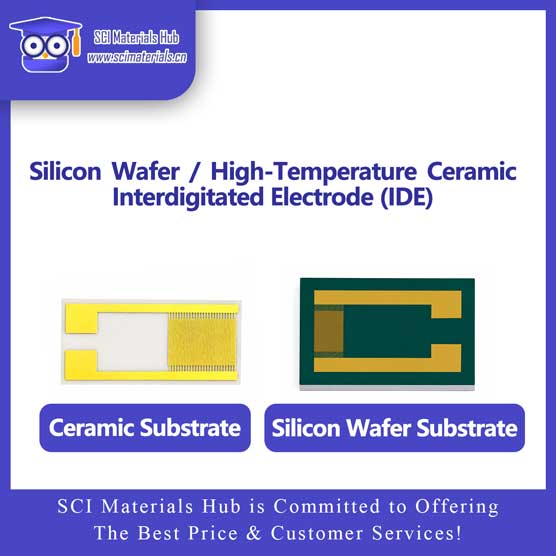
Silicon Wafer / High-Temperature Ceramic Interdigitated Electrode (IDE)

  • Product Code:
  • Description:Silicon Wafer / High-Temperature Ceramic Interdigitated Electrode (IDE)
  • Brand:SCI Materials Hub
  • Lead time:ASK for Quote
  • Views:
  • Telephone:+86 153-5789-9751; +86 156-0553-2352
  • Keywords:Silicon Wafer / High-Temperature Ceramic Interdigitated Electrode (IDE), SCI Materials Hub
Ceramic and Silicon Interdigitated Electrodes (IDE)
HIGH-PRECISION INTERDIGITATED ELECTRODE

Ceramic Interdigitated Electrode & Silicon Interdigitated Electrode

Built on high-insulation alumina ceramic or high-flatness silicon substrates, combined with micron-scale circuit patterning and multilayer metal deposition, providing a stable, precise, and easy-to-integrate microelectrode platform for electrochemical analysis, impedance testing, gas sensing, biochips, microfluidic integration, and MEMS device research.

Micron-Scale Line Width / Spacing Ceramic / Silicon Dual Substrates Au / Ni / Cu / Ti MEMS Process Compatible Array and Custom Pattern Support
Alumina Ceramic Substrate
High-Flatness Silicon Substrate
μm High-Precision Microstructure Supports 50 μm, 100 μm, and Custom Designs
Al₂O₃ / Si Ceramic and Silicon Dual-Substrate Options
50 μm+ Multiple Line Width / Spacing Options
Au/Ni/Cu/Ti Multilayer Metal Composite Structure
OEM / ODM Custom Sizes, Arrays, and Special Patterns
IDE Principle

What Is an Interdigitated Electrode?

An interdigitated electrode consists of two comb-shaped metal electrode sets that interlock while remaining electrically insulated from each other. Micron-scale interdigitated traces increase the effective boundary length within a limited area, forming a concentrated and uniform local electric field to improve the sensitivity of impedance, capacitance, conductance, and interfacial-reaction measurements.

INTERDIGITATED MICROELECTRODE

Amplify Electrical Responses from Materials and Interfaces Using Interdigitated Microelectrodes

When liquids, thin films, gas-sensitive materials, biorecognition layers, or dielectric materials cover the interdigitated area, the resistance, capacitance, and impedance between the two electrode sets change with material state, concentration, humidity, adsorption behavior, or chemical reactions, enabling high-sensitivity detection.

Suitable for in-situ electrical testing of trace liquids, thin-film materials, gas adsorption layers, biomolecules, and micro/nanostructured devices.

Higher Electric-Field Concentration

Micron-scale spacing shortens the electric-field interaction distance, improving the detection capability for local material changes.

Enhanced Interfacial Response

A longer effective electrode boundary increases the interaction area between the sample and the electrode.

Reduced Measurement Noise

Highly consistent traces and stable insulating substrates help produce cleaner test signals.

Easy Chip Integration

Can be integrated with microchannels, functional coatings, packaging circuits, and MEMS structures.

Product Series

Dual Series: Ceramic IDE and Silicon IDE

Select alumina ceramic or silicon substrates according to temperature resistance, insulation performance, processing precision, semiconductor-process compatibility, and chip-integration requirements.

🧩 Ceramic Interdigitated Electrode

A Stable Test Platform with High Insulation and High Temperature Resistance

Uses high-insulation alumina ceramic as the substrate, with precision thin-film deposition, fine-line patterning, and multilayer metal plating to form the IDE structure. It offers temperature resistance, acid/alkali resistance, low dielectric loss, and dimensional stability, making it suitable for complex environments and long-duration experiments.

  • High-resistivity substrate with low leakage current, suitable for weak-signal detection
  • Low dielectric loss, suitable for impedance and high-frequency dielectric testing
  • Good temperature and chemical resistance, suitable for complex experimental systems
  • Dimensionally stable under high-temperature conditions with minimal deformation
  • Suitable for long-term cycling, electrochemical, and gas-sensitive material testing
⚡ Silicon Interdigitated Electrode

A High-Flatness, High-Precision Micro/Nano Device Platform

Uses high-flatness silicon wafers as substrates and is compatible with photolithography, thin-film deposition, micro/nanofabrication, MEMS, and semiconductor packaging processes. Suitable for finer line widths, more complex patterns, and chip-level array designs, and easy integration with microchannels, sensing units, and electronic structures.

  • High surface flatness, suitable for fine photolithography and micro/nano patterning
  • Compatible with MEMS, semiconductor, and chip-packaging processes
  • Suitable for finer line widths, denser IDE fingers, and complex array structures
  • Can be integrated with microchannels, sensing films, and optoelectronic devices
  • Suitable for biochips, micro/nano sensing, and device prototype development
Metal Layer Structure

Multilayer Metal Composite Electrode Structure

Typical products use an Au / Ni / Cu / Ti multilayer metal system, providing anti-oxidation, barrier transition, main conduction, and adhesion-enhancement functions.

Au Gold Layer · Approx. 1 U Ni Nickel Layer · Approx. 3 μm Cu Copper Layer · Approx. 12 μm Ti Titanium Layer · Approx. 0.1 μm Ceramic / Silicon Substrate
Au

Gold Surface Layer

Typical thickness is about 1 U, providing good conductivity, oxidation resistance, and surface chemical stability, facilitating electrochemical modification and biomolecule immobilization.

Ni

Nickel Transition / Barrier Layer

Typical thickness is about 3 μm, serving as a transition layer between gold and copper, reducing metal diffusion and improving multilayer structural stability.

Cu

Copper Main Conductive Layer

Typical thickness is about 12 μm, providing the main current conduction path, suitable for forming IDE traces, pads, and external connection structures.

Ti

Titanium Adhesion Layer

Typical thickness is about 0.1 μm, used to enhance the bonding strength between metal traces and ceramic or silicon wafer surfaces, improving structural reliability.

Substrate Comparison

Parameter Comparison: Ceramic Substrate vs Silicon Substrate

Ceramic substrates emphasize insulation, temperature resistance, low dielectric loss, and long-term stability; silicon substrates emphasize surface flatness, processing precision, and MEMS process compatibility.

Comparison Parameter
Alumina Ceramic

Alumina Ceramic Substrate

High insulation, low loss, and temperature-stable

Silicon Wafer

Silicon Substrate

High flatness and micro/nanofabrication compatibility

Substrate MaterialHigh-insulation alumina Al₂O₃ ceramicMonocrystalline silicon or specified silicon wafer type, with optional insulating layer
Typical Temperature Resistance Reference Approx. -200 °C to 350 °C Suitable for chip-level thermal processing and experimental environments
Insulation PerformanceHigh resistivity and low leakage current, with good substrate insulation stabilityUsually designed together with an oxide layer or insulating structure, to meet semiconductor device requirements
Dielectric LossLow dielectric loss, typical tanδ can be below 0.001Depends on wafer type, frequency, and insulating-layer structure
Thermal ConductivityApprox. 15–30 W/(m·K), with good heat-dissipation capabilitySilicon has good thermal conductivity, suitable for chip-level thermal management studies
Surface FlatnessGood flatness, suitable for standard micron-scale tracesExtremely high surface flatness, suitable for fine photolithography and micro/nanofabrication
Patterning PrecisionSuitable for 50 μm, 100 μm, and standard micron-scale designsSuitable for finer line widths, higher density, and complex pattern designs
Chemical StabilityAlumina ceramic offers strong acid and alkali resistance, suitable for complex experimental environmentsDepends on the surface oxide layer, packaging layer, and experimental media
Mechanical PropertiesDimensionally stable, but it is a brittle material, so impacts should be avoided during useSuitable for wafer processing and chip packaging, while bending and impact should also be avoided
Process CompatibilityCompatible with thin-film deposition, electroplating, and standard microtrace fabricationHighly compatible with MEMS, semiconductor, photolithography, and micro/nanofabrication systems
Typical ApplicationsElectrochemistry, gas sensing, high-frequency dielectric, and long-term impedance testingMEMS, biochips, microfluidics, optoelectronic and micro/nano device development
Recommended Scenarios Focus on temperature resistance, insulation, and long-term stability Focus on precision, integration, and process compatibility
Note: The temperature, dielectric loss, and thermal conductivity values in the table are reference ranges for materials and typical products. Actual performance is affected by ceramic purity, silicon wafer type, insulating layer, metal-layer thickness, packaging structure, pattern dimensions, and experimental media, and the specific use conditions should follow actual product specifications and test results.
Specifications

Product Specifications and Custom Parameters

Supports ceramic and silicon substrates, multiple noble-metal systems, micron-scale line width and spacing, different finger-pair counts, array channels, and special pattern designs.

ParameterStandard OptionsCustomizable ItemsSelection Notes
Substrate TypeAlumina Ceramic / Silicon WaferCeramic purity, silicon wafer type, and insulating layerSelect based on temperature, insulation, and process requirements
Overall SizeMultiple standard chip sizesLength/width, round wafers, and irregular outlinesDetermined by fixture, flow-channel, and packaging space
Line Width50 μm, 100 μm, etc.Supports finer or special combination designsAffects resistance, sensitivity, and fabrication difficulty
Line Spacing50 μm, 100 μm, etc.Supports unequal line width and spacing designsSmaller spacing creates a more concentrated local electric field
Finger LengthConfigured according to the standard active areaSupports specified finger lengthAffects effective sensing area and boundary length
Finger-Pair CountMultiple specifications availablePair count, total finger count, and arrangement densityAffects capacitance, impedance, and signal response
Metal SystemAu / Ni / Cu / TiAu, Pt, Ag, Cu, and other systemsSelect according to the potential window and experimental media
Typical ThicknessAu 1 U、Ni 3 μm、 Cu 12 μm、Ti 0.1 μmSupports adjustment of metal-layer thicknessAffects conductivity, adhesion, and durability
Channel FormSingle-channel IDEDual-channel, multi-channel, and array designsSuitable for control experiments and multi-point synchronous detection
Connection MethodPads, probes, and clamp connectionsLeads, flat cables, and dedicated interfacesDetermined by instrument and packaging method
Special StructuresStandard rectangular interdigitated patternRing, arc, array, and microfluidic-integrated designsAdaptable to MEMS, biochips, and sensor arrays
Core Features

Core Product Features

Combines precision structure, signal stability, substrate insulation, surface oxidation resistance, and micro/nano device integration capability.

μm

Micron-Scale Line Width / Spacing

Supports 50 μm, 100 μm, and higher-precision pattern designs, with adjustable line width, line spacing, and finger length according to sensitivity and active-area requirements.

50 μm 100 μm Fine Pattern Customization

Highly Consistent IDE Structure

Precision circuit fabrication ensures regular IDE arrangement and clear boundaries, helping achieve a uniform electric field and high test repeatability.

Uniform Electric Field High Repeatability Low Signal Noise
Au

Stable Noble-Metal Surface

The gold surface layer provides good oxidation resistance and conductivity, suitable for long-term testing, electrochemical modification, and biofunctionalization.

Oxidation Resistance Surface Modification Long-Term Stability

High Insulation and High Integration Capability

The ceramic substrate provides stable insulation and low dielectric loss, while the silicon substrate supports MEMS, photolithography, and microfluidic integration.

High Insulation MEMS Compatible Chip Integration
Applications

Typical Application Areas

Can be used as a standalone test electrode or integrated with functional materials, microchannels, biorecognition layers, packaging circuits, and micro/nanostructures.

01 🧪

Electrochemical Research

Used for impedance, conductance, capacitance, electrode reactions, and interfacial process analysis.

02 🌫

Gas and Humidity Sensing

Combined with gas-sensitive, humidity-sensitive, or porous materials, to detect VOCs, humidity, and gas adsorption behavior.

03 🧬

Biosensing

Used for DNA, proteins, biomolecules, and electrochemical biochip research.

04 📡

High-Frequency Dielectric Testing

Suitable for microwave and high-frequency materials, dielectric constant, and loss-property studies.

05 💧

Microfluidic Systems

Integrated with lab-on-a-chip channels, enabling in-situ detection of trace samples.

06

Flexible Electronics and Transfer Printing

Used for conductive structures, transfer-printing processes, and flexible device prototype research.

07 🖥

MEMS Devices

Suitable for micro/nanostructures, chip-level sensors, and array-device development.

08

Electrical Testing of Materials

Used for thin films, slurries, polymers, nanomaterials, and dielectric material analysis.

Selection Guide

How to Choose Between Ceramic IDE and Silicon IDE?

Select based on experiment temperature, medium corrosiveness, insulation requirements, pattern precision, and micro/nano process integration needs.

Recommended: Ceramic-Substrate IDE

For temperature resistance, insulation, and long-term stability

Suitable for high-temperature, corrosion-resistant, low-dielectric-loss, and long-duration testing, especially electrochemical, gas-sensing, and high-frequency dielectric experiments.

  • High-Temperature Experiments
  • Acid/Alkali Environments
  • Long-Term Impedance Testing
  • High-Frequency Dielectric Research
  • Gas-Sensitive Material Testing
  • Stable Insulation Requirements
Recommended: Silicon-Substrate IDE

For precision, integration, and MEMS compatibility

Suitable for fine photolithography, micro/nano sensing, microfluidics, biochips, optoelectronic devices, and array-based integrated development.

  • MEMS Devices
  • Microfluidic Chips
  • Biosensors
  • Complex Micro/Nano Patterns
  • Array Design
  • Semiconductor Processes
Customization Process

IDE Customization Process

From application requirements and pattern parameters to substrate materials and metal structures, we provide complete custom design and sample verification services.

01

Confirm Experimental Requirements

Provide the test object, medium, temperature, frequency, and detection method.

02

Select Substrate Structure

Confirm ceramic or silicon, size, thickness, and insulating layer.

03

Confirm Pattern Parameters

Confirm line width, line spacing, finger length, pair count, pads, and array structure.

04

Sample Fabrication and Verification

Complete drawing confirmation, sample fabrication, and subsequent test optimization.

Customize Dedicated IDE Microelectrodes for Your Experiment

Provide substrate type, overall size, substrate thickness, line width, line spacing, finger length, finger-pair count, metal system, coating thickness, channel count, and connection method for custom solution evaluation.

Comprehensive Price Table

Overall SizeFinger PairsLine Width/Spacing (um/um)SubstrateAliExpressAmazon SKUPrice ($)
10*10mm15 Pairs80/80High-Temperature Ceramic1010-15P-80W80S-HTCIDE-1010-15P-80W80S-HTC$18
10*10mm15 Pairs100/50High-Temperature Ceramic1010-15P-100W50S-HTCIDE-1010-15P-100W50S-HTC$22
10*20mm25 Pairs100/50High-Temperature Ceramic1020-25P-100W50S-HTCIDE-1020-25P-100W50S-HTC$34
6*4mm25 Pairs10/10Silicon Substrate0604-25P-100W100S-SIIDE-0604-25P-100W100S-SI$46
6*4mm25 Pairs20/20Silicon Substrate0604-25P-20W20S-SIIDE-0604-25P-20W20S-SI$46
6*4mm25 Pairs30/30Silicon Substrate0604-25P-30W30S-SIIDE-0604-25P-30W30S-SI$42

International Orders & Shipping

📞 WhatsApp & Tel: +86 153-7569-8751
🔗 Place quick orders on our eBay / Amazon / Alibaba stores.
🌐 We ship worldwide via DHL, FedEx, UPS, SF-Express, or other requested carriers.
📦 Bulk quantities with discount available upon request.
💳 Payment methods accepted: Bank Wire Transfer, PayPal, Credit Card (via Taobao), Alipay, WeChat Pay


Partial references citing our materials (from Google Scholar)

Carbon Dioxide Reduction

1. ACS Nano Strain Relaxation in Metal Alloy Catalysts Steers the Product Selectivity of Electrocatalytic CO2 Reduction

The bipolar membrane (Fumasep FBM) in this paper was purchased from SCI Materials Hub, which was used in rechargeable Zn-CO2 battery tests. The authors reported a strain relaxation strategy to determine lattice strains in bimetal MNi alloys (M = Pd, Ag, and Au) and realized an outstanding CO2-to-CO Faradaic efficiency of 96.6% with outstanding activity and durability toward a Zn-CO2 battery.


2. Front. Chem. Boosting Electrochemical Carbon Dioxide Reduction on Atomically Dispersed Nickel Catalyst

In this paper, Vulcan XC-72R was purchased from SCI Materials Hub. Vulcan XC 72R carbon is the most common catalyst support used in the anode and cathode electrodes of Polymer Electrolyte Membrane Fuel Cells (PEMFC), Direct Methanol Fuel Cells (DMFC), Alkaline Fuel Cells (AFC), Microbial Fuel Cells (MFC), Phosphoric Acid Fuel Cells (PAFC), and many more!


3. Adv. Mater. Partially Nitrided Ni Nanoclusters Achieve Energy-Efficient Electrocatalytic CO2 Reduction to CO at Ultralow Overpotential

An AEM membrane (Sustainion X37-50 Grade RT, purchased from SCI Materials Hub) was activated in 1 M KOH for 24 h, washed with ultra-purity water prior to use.


4. Adv. Funct. Mater. Nanoconfined Molecular Catalysts in Integrated Gas Diffusion Electrodes for High-Current-Density CO2 Electroreduction

In this paper (Supporting Information), an anion exchanged membrane (Fumasep FAB-PK-130 obtained from SCI Materials Hub (www.scimaterials.cn)) was used to separate the catholyte and anolyte chambers.

SCI Materials Hub: we also recommend our Fumasep FAB-PK-75 for the use in a flow cell.


5. Appl. Catal. B Efficient utilization of nickel single atoms for CO2 electroreduction by constructing 3D interconnected nitrogen-doped carbon tube network

In this paper, the Nafion 117 membrane was obtained from SCI Materials Hub.


6. Vacuum Modulable Cu(0)/Cu(I)/Cu(II) sites of Cu/C catalysts derived from MOF for highly selective CO2 electroreduction to hydrocarbons

In this paper, Proton exchange membrane (Nafion 117), Nafion D520, and Toray 060 carbon paper were purchased from SCI Materials Hub.


7. National Science Review Confinement of ionomer for electrocatalytic CO2 reduction reaction via efficient mass transfer pathways

An anion exchange membrane (PiperION-A15-HCO3) was obtained from SCI Materials Hub.


8. Catalysis Communications Facilitating CO2 electroreduction to C2H4 through facile regulating {100} & {111} grain boundary of Cu2O

Carbon paper (TGPH060), membrane solution (Nafion D520), and ionic membrane (Nafion N117) were obtained from Wuhu Eryi Material Technology Co., Ltd (a company under SCI Materials Hub).


Batteries

1. J. Mater. Chem. A Blocking polysulfides with a Janus Fe3C/N-CNF@RGO electrode via physiochemical confinement and catalytic conversion for high-performance lithium–sulfur batteries

Graphene oxide (GO) in this paper was obtained from SCI Materials Hub. The authors introduced a Janus Fe3C/N-CNF@RGO electrode consisting of 1D Fe3C decorated N-doped carbon nanofibers (Fe3C/N-CNFs) side and 2D reduced graphene oxide (RGO) side as the free-standing carrier of Li2S6 catholyte to improve the overall electrochemical performance of Li-S batteries.


2. Joule A high-voltage and stable zinc-air battery enabled by dual-hydrophobic-induced proton shuttle shielding

This paper used more than 10 kinds of materials from SCI Materials Hub and the authors gave detailed properity comparsion.

The commercial IEMs of Fumasep FAB-PK-130 and Nafion N117 were obtained from SCI Materials Hub.

Gas diffusion layers of GDL340 (CeTech) and SGL39BC (Sigracet) and Nafion dispersion (Nafion D520) were obtained from SCI Materials Hub.

Zn foil (100 mm thickness) and Zn powder were obtained from the SCI Materials Hub.

Commercial 20% Pt/C, 40% Pt/C and IrO2 catalysts were also obtained from SCI Materials Hub.


3. Journal of Energy Chemistry Vanadium oxide nanospheres encapsulated in N-doped carbon nanofibers with morphology and defect dual-engineering toward advanced aqueous zinc-ion batteries

In this paper, carbon cloth (W0S1011) was obtained from SCI Materials Hub. The flexible carbon cloth matrix guaranteed the stabilization of the electrode and improved the conductivity of the cathode.


4. Energy Storage Materials Defect-abundant commercializable 3D carbon papers for fabricating composite Li anode with high loading and long life

The 3D carbon paper (TGPH060 raw paper) were purchased from SCI Materials Hub.


5. Nanomaterials A Stable Rechargeable Aqueous Zn–Air Battery Enabled by Heterogeneous MoS2 Cathode Catalysts

Nafion D520 (5 wt%), and carbon paper (GDL340) were received from SCI-Materials-Hub.


6. SSRN An Axially Directed Cobalt-Phthalocyanine Covalent Organic Polymer as High-Efficient Bifunctional Catalyst for Zn-Air Battery

Carbon cloth (W0S1011) and other electrochemical consumables required for air cathode were provided by SCI Materials Hub.


Oxygen Reduction Reaction

1. J. Chem. Eng. Superior Efficiency Hydrogen Peroxide Production in Acidic Media through Epoxy Group Adjacent to Co-O/C Active Centers on Carbon Black

In this paper, Vulcan XC 72 carbon black, ion membrane (Nafion N115, 127 μL), Nafion solution (D520, 5 wt%), and carbon paper (AvCarb GDS 2230 and Spectracarb 2050A-1050) were purchased from SCI Materials Hub.


2. Journal of Colloid and Interface Science Gaining insight into the impact of electronic property and interface electrostatic field on ORR kinetics in alloy engineering via theoretical prognostication and experimental validation

The 20 wt% Pt3M (M = Cr, Co, Cu, Pd, Sn, and Ir) were purchased from SCI Materials Hub. This work places emphasis on the kinetics of the ORR concerning Pt3M (M = Cr, Co, Cu, Pd, Sn, and Ir) catalysts, and integrates theoretical prognostication and experimental validation to illuminate the fundamental principles of alloy engineering.


Water Electrolysis

1. International Journal of Hydrogen Energy Gold as an efficient hydrogen isotope separation catalyst in proton exchange membrane water electrolysis

The cathodic catalysts of Pt/C (20 wt%, 2–3 nm) and Au/C (20 wt%, 4–5 nm) were purchased from SCI Materials Hub.


2. Small Science Silver Compositing Boosts Water Electrolysis Activity and Durability of RuO2 in a Proton-Exchange-Membrane Water Electrolyzer

Two fiber felts (0.35 mm thickness, SCI Materials Hub) were used as the porous transport layers at both the cathode and the anode.


3. Advanced Functional Materials Hierarchical Crystalline/Amorphous Heterostructure MoNi/NiMoOx for Electrochemical Hydrogen Evolution with Industry-Level Activity and Stability

Anion-exchange membrane (FAA-3-PK-130) was obtained from SCI Materials Hub website.


Fuel Cells

1. Polymer Sub-two-micron ultrathin proton exchange membrane with reinforced mechanical strength

Gas diffusion electrode (60% Pt/C, Carbon paper) was purchased from SCI Materials Hub.


Characterization

1. Chemical Engineering Journal Electrochemical reconstitution of Prussian blue analogue for coupling furfural electro-oxidation with photo-assisted hydrogen evolution reaction

An Au nanoparticle film was deposited on the total reflecting plane of a single reflection ATR crystal (SCI Materials Hub, Wuhu, China) via sputter coater.


Related Products

We Provide A Broad Range of Materials, Instruments & Solutions in Advanced Science and Technologies About Us
Product consultation
Customer service1
Customer service2
After-sales and technical consultation
Customer service1
Customer service2
WeChat Customer Service

Back to top