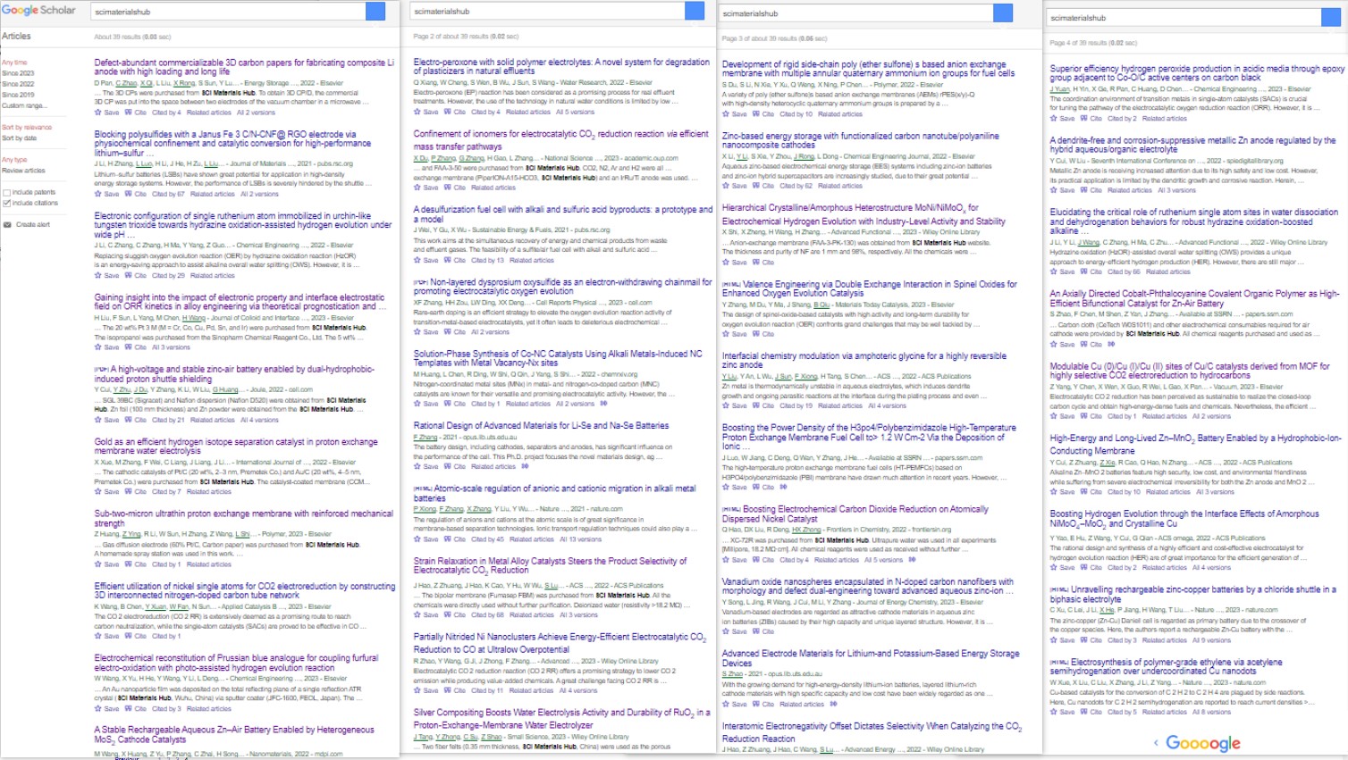
Partial references citing our materials (from Google Scholar)
Carbon Dioxide Reduction
1. ACS Nano Strain Relaxation in Metal Alloy Catalysts Steers the Product Selectivity of Electrocatalytic CO2 Reduction
The bipolar membrane (Fumasep FBM) in this paper was purchased from SCI Materials Hub, which was used in rechargeable Zn-CO2 battery tests. The authors reported a strain relaxation strategy to determine lattice strains in bimetal MNi alloys (M = Pd, Ag, and Au) and realized an outstanding CO2-to-CO Faradaic efficiency of 96.6% with outstanding activity and durability toward a Zn-CO2 battery.
2. Front. Chem. Boosting Electrochemical Carbon Dioxide Reduction on Atomically Dispersed Nickel Catalyst
In this paper, Vulcan XC-72R was purchased from SCI Materials Hub. Vulcan XC 72R carbon is the most common catalyst support used in the anode and cathode electrodes of Polymer Electrolyte Membrane Fuel Cells (PEMFC), Direct Methanol Fuel Cells (DMFC), Alkaline Fuel Cells (AFC), Microbial Fuel Cells (MFC), Phosphoric Acid Fuel Cells (PAFC), and many more!
3. Adv. Mater. Partially Nitrided Ni Nanoclusters Achieve Energy-Efficient Electrocatalytic CO2 Reduction to CO at Ultralow Overpotential
An AEM membrane (Sustainion X37-50 Grade RT, purchased from SCI Materials Hub) was activated in 1 M KOH for 24 h, washed with ultra-purity water prior to use.
4. Adv. Funct. Mater. Nanoconfined Molecular Catalysts in Integrated Gas Diffusion Electrodes for High-Current-Density CO2 Electroreduction
In this paper (Supporting Information), an anion exchanged membrane (Fumasep FAB-PK-130 obtained from SCI Materials Hub (www.scimaterials.cn)) was used to separate the catholyte and anolyte chambers.
SCI Materials Hub: we also recommend our Fumasep FAB-PK-75 for the use in a flow cell.
5. Appl. Catal. B Efficient utilization of nickel single atoms for CO2 electroreduction by constructing 3D interconnected nitrogen-doped carbon tube network
In this paper, the Nafion 117 membrane was obtained from SCI Materials Hub.
6. Vacuum Modulable Cu(0)/Cu(I)/Cu(II) sites of Cu/C catalysts derived from MOF for highly selective CO2 electroreduction to hydrocarbons
In this paper, Proton exchange membrane (Nafion 117), Nafion D520, and Toray 060 carbon paper were purchased from SCI Materials Hub.
7. National Science Review Confinement of ionomer for electrocatalytic CO2 reduction reaction via efficient mass transfer pathways
An anion exchange membrane (PiperION-A15-HCO3) was obtained from SCI Materials Hub.
8. Catalysis Communications Facilitating CO2 electroreduction to C2H4 through facile regulating {100} & {111} grain boundary of Cu2O
Carbon paper (TGPH060), membrane solution (Nafion D520), and ionic membrane (Nafion N117) were obtained from Wuhu Eryi Material Technology Co., Ltd (a company under SCI Materials Hub).
Batteries
1. J. Mater. Chem. A Blocking polysulfides with a Janus Fe3C/N-CNF@RGO electrode via physiochemical confinement and catalytic conversion for high-performance lithium–sulfur batteries
Graphene oxide (GO) in this paper was obtained from SCI Materials Hub. The authors introduced a Janus Fe3C/N-CNF@RGO electrode consisting of 1D Fe3C decorated N-doped carbon nanofibers (Fe3C/N-CNFs) side and 2D reduced graphene oxide (RGO) side as the free-standing carrier of Li2S6 catholyte to improve the overall electrochemical performance of Li-S batteries.
2. Joule A high-voltage and stable zinc-air battery enabled by dual-hydrophobic-induced proton shuttle shielding
This paper used more than 10 kinds of materials from SCI Materials Hub and the authors gave detailed properity comparsion.
The commercial IEMs of Fumasep FAB-PK-130 and Nafion N117 were obtained from SCI Materials Hub.
Gas diffusion layers of GDL340 (CeTech) and SGL39BC (Sigracet) and Nafion dispersion (Nafion D520) were obtained from SCI Materials Hub.
Zn foil (100 mm thickness) and Zn powder were obtained from the SCI Materials Hub.
Commercial 20% Pt/C, 40% Pt/C and IrO2 catalysts were also obtained from SCI Materials Hub.
3. Journal of Energy Chemistry Vanadium oxide nanospheres encapsulated in N-doped carbon nanofibers with morphology and defect dual-engineering toward advanced aqueous zinc-ion batteries
In this paper, carbon cloth (W0S1011) was obtained from SCI Materials Hub. The flexible carbon cloth matrix guaranteed the stabilization of the electrode and improved the conductivity of the cathode.
4. Energy Storage Materials Defect-abundant commercializable 3D carbon papers for fabricating composite Li anode with high loading and long life
The 3D carbon paper (TGPH060 raw paper) were purchased from SCI Materials Hub.
5. Nanomaterials A Stable Rechargeable Aqueous Zn–Air Battery Enabled by Heterogeneous MoS2 Cathode Catalysts
Nafion D520 (5 wt%), and carbon paper (GDL340) were received from SCI-Materials-Hub.
6. SSRN An Axially Directed Cobalt-Phthalocyanine Covalent Organic Polymer as High-Efficient Bifunctional Catalyst for Zn-Air Battery
Carbon cloth (W0S1011) and other electrochemical consumables required for air cathode were provided by SCI Materials Hub.
Oxygen Reduction Reaction
1. J. Chem. Eng. Superior Efficiency Hydrogen Peroxide Production in Acidic Media through Epoxy Group Adjacent to Co-O/C Active Centers on Carbon Black
In this paper, Vulcan XC 72 carbon black, ion membrane (Nafion N115, 127 μL), Nafion solution (D520, 5 wt%), and carbon paper (AvCarb GDS 2230 and Spectracarb 2050A-1050) were purchased from SCI Materials Hub.
2. Journal of Colloid and Interface Science Gaining insight into the impact of electronic property and interface electrostatic field on ORR kinetics in alloy engineering via theoretical prognostication and experimental validation
The 20 wt% Pt3M (M = Cr, Co, Cu, Pd, Sn, and Ir) were purchased from SCI Materials Hub. This work places emphasis on the kinetics of the ORR concerning Pt3M (M = Cr, Co, Cu, Pd, Sn, and Ir) catalysts, and integrates theoretical prognostication and experimental validation to illuminate the fundamental principles of alloy engineering.
Water Electrolysis
1. International Journal of Hydrogen Energy Gold as an efficient hydrogen isotope separation catalyst in proton exchange membrane water electrolysis
The cathodic catalysts of Pt/C (20 wt%, 2–3 nm) and Au/C (20 wt%, 4–5 nm) were purchased from SCI Materials Hub.
2. Small Science Silver Compositing Boosts Water Electrolysis Activity and Durability of RuO2 in a Proton-Exchange-Membrane Water Electrolyzer
Two fiber felts (0.35 mm thickness, SCI Materials Hub) were used as the porous transport layers at both the cathode and the anode.
3. Advanced Functional Materials Hierarchical Crystalline/Amorphous Heterostructure MoNi/NiMoOx for Electrochemical Hydrogen Evolution with Industry-Level Activity and Stability
Anion-exchange membrane (FAA-3-PK-130) was obtained from SCI Materials Hub website.
Fuel Cells
1. Polymer Sub-two-micron ultrathin proton exchange membrane with reinforced mechanical strength
Gas diffusion electrode (60% Pt/C, Carbon paper) was purchased from SCI Materials Hub.
Characterization
1. Chemical Engineering Journal Electrochemical reconstitution of Prussian blue analogue for coupling furfural electro-oxidation with photo-assisted hydrogen evolution reaction
An Au nanoparticle film was deposited on the total reflecting plane of a single reflection ATR crystal (SCI Materials Hub, Wuhu, China) via sputter coater.